Tolerance refers to the allowable variation in the dimensions or geometric parameters of a part during machining. It is used to control the distribution of manufacturing errors, ensuring part interchangeability and proper assembly function.

In machining, due to influences such as material properties, temperature changes, and clamping errors, tolerance ranges are specified on drawings. These variations typically follow a normal distribution.
Tolerances are categorized into:
- Dimensional tolerance – the absolute value of the algebraic difference between the maximum and minimum limit dimensions.
- Form tolerance (covering 6 measurement items) – the total permissible variation in the shape of a single feature, including straightness, flatness, roundness, cylindricity, profile of a line, and profile of a surface.
- Position (location) tolerance (covering 8 measurement items) – the total permissible variation in the position of a feature relative to a datum, governing relationships between two or more points, lines, or surfaces. This includes parallelism, perpendicularity, angularity, concentricity, symmetry, position, circular runout, and total runout.
Tolerance grades range from IT01 to IT18, totaling 20 levels, with values increasing as the grade decreases.
- IT5 to IT13 are commonly used for fit dimensions.
- IT12 to IT18 are often applied to non‑fit dimensions.
Tighter tolerances increase machining difficulty, often requiring special tools and multiple processes, which can raise rejection rates and inspection costs.
3D scanning inspection technology enables rapid geometric tolerance measurement by aligning coordinate systems and analyzing deviations via color maps, with the highest accuracy reaching 0.025 mm.
Setting tolerances requires balancing machining capability, assembly needs, and cost control. Where possible, general tolerances should be preferred to reduce costs without compromising functionality.
Basic Meaning
In machine design and manufacturing, tolerance is the allowable variation in the actual parameter values of a component or part. For example, if the upper and lower limits of a product specification are 100 and 60, the tolerance is 40; if the limits are +100 and –100, the tolerance is 200.
These parameters include not only geometric quantities in machining, but also physical, chemical, electrical, and other parameters. Thus, tolerance is a broadly applicable concept. In mechanical manufacturing, the purpose of specifying tolerances is to define geometric parameters so that their variations remain within a certain range, thereby achieving interchangeability or fit requirements.
Geometric tolerances include dimensional, form, and position tolerances.
Classification
- Dimensional tolerance – the allowable variation in size, equal to the absolute value of the algebraic difference between the maximum and minimum limit sizes.
- Form tolerance – the total permissible variation in the shape of a single feature, covering the six items listed above.
- Position tolerance – the total permissible variation in the location of a feature relative to a datum, covering the eight items listed above.
Tolerance reflects the required manufacturing precision of a part and indicates the difficulty of its machining.
Tolerance grades are designated IT01, IT0, IT1, …, IT18 (20 grades in total), with precision decreasing and tolerance values increasing from IT01 to IT18. “IT” stands for International Tolerance.
Selection Principles
The fundamental rule for selecting tolerance values is to achieve the best overall economic effect considering both production cost and product usability.
- General fit dimensions: IT5–IT13
- Extra‑precision fit dimensions: IT2–IT5
- Non‑fit dimensions: IT12–IT18
- Raw material fits: IT8–IT14
Setting Tolerances
Tolerance specification should meet the following requirements:
- Match manufacturing capability – Tolerances that exceed production capabilities are meaningless.
- Meet product requirements – Through tolerance analysis, specified tolerances must satisfy assembly, function, appearance, and quality needs.
- Balance with cost – Tighter tolerances increase cost; where possible, the most lenient tolerances that meet all requirements should be selected.
- Optimize design features – Well‑designed product features can allow looser tolerances, reducing production costs.
Standard Tolerances (Mechanical)
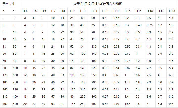
According to international standards, the following is a standard tolerance table for basic sizes 0–500 mm and grades IT4–IT18.
(Note: For basic sizes below 1 mm, grades IT14–IT18 are not defined.)