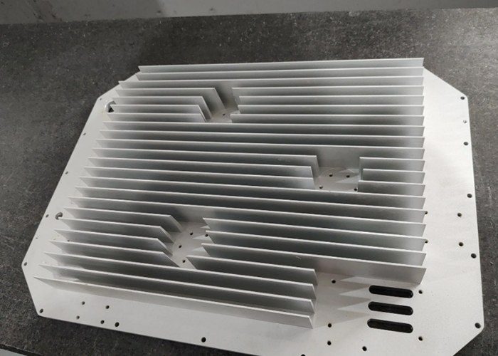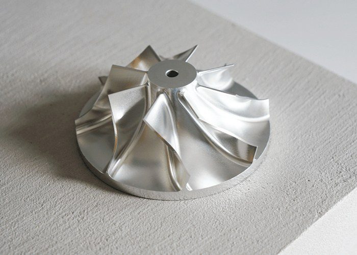
I. Material Pre-Treatment in Precision CNC Machining (Reduce Tool Marks and Pinholes at the Source)
- Aluminum (6061/7075 – mainstream for fixtures)
- Use extruded fine-quality stock; avoid recycled or mixed aluminum scrap.
- Perform stress-relief aging on the blank before machining to reduce chatter-induced waviness.
- Remove oxide scale and surface scratches by grinding/polishing the blank surface.
- Stainless Steel
- Use precision cold-rolled sheets. Hot-rolled sheets have rough surfaces and are difficult to polish to a bright finish in finishing operations.
- Reject blanks with pitting or cracks.
- Plastics (POM/PTFE)
- Use high‑purity unfilled raw materials. Glass‑filled plastics are inherently matte and cannot achieve a high‑gloss finish.
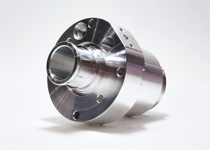
II. Tool Selection (Core Factor for High Gloss – Significant Differences)
1. Tool Material
- Aluminum high‑gloss machining:
- Diamond PCD end mills (first choice for mirror finish) > ultra‑fine grain carbide high‑gloss cutters (uncoated or nano‑diamond coated).
- Avoid ordinary TiN‑coated tools; coating particles will leave fine scratches.
- Stainless steel high‑gloss:
- Dedicated mirror‑finish tungsten steel tools for stainless steel, with TiSiN coating and sharp large rake angles.
- Plastics:
- Uncoated high‑gloss high‑speed steel tools or polished tungsten steel cutters.
2. Tool Geometry & Parameters
- Cutting edge:
- Mirror‑polished edge, free from chipping and burrs.
- Slight edge honing/radius of 0.02–0.03 mm to prevent built‑up edge and dragging on the surface.
- Helix angle:
- For aluminum, use 45°–55° large helix angle for smooth chip evacuation without rubbing the machined surface.
- Number of flutes:
- For finishing, use 2‑flute tools (larger chip space); avoid 4‑flute tools to reduce chip‑jamming scratches.
- Corner radius (nose R):
- For finishing, choose small R0.2–R0.8 mm to produce finer feed marks and better gloss.
III. Cutting Parameter Optimization (Determines Fineness of Feed Marks)
1. Standard High‑Gloss Parameters for Aluminum Alloy (6061)
- Spindle speed S: 12,000–30,000 rpm (on high‑speed engraving/milling or high‑speed machines).
- Feed rate F: 0.1–0.3 mm/rev – lower feed reduces cutting marks.
- Depth of cut ap: Multi‑step finishing, each layer ≤0.05 mm – extremely light cuts to avoid squeezing marks.
- Stepover: 1/8 to 1/4 of the tool nose radius. Smaller stepover gives finer, denser feed marks and doubles the gloss level.
- Example: with an R0.4 tool, stepover ≤0.05 mm makes tool marks almost invisible to the naked eye.
2. Stainless Steel High‑Gloss
- Use lower spindle speed and higher feed: S 3,000–6,000 rpm, with ample coolant to prevent built‑up edge and orange‑peel surfaces.
3. Taboos
- Low speed, large depth of cut, and wide stepover will create wavy tool marks that are difficult to polish to a high gloss later.
IV. Cooling and Chip Evacuation (Prevent Scratches and Tearing)
- Dry cutting for aluminum mirror finish:
- High‑speed PCD tools can run dry, leaving no coolant residue or water spots, giving the best gloss.
- For ordinary tungsten steel tools, use pure kerosene or dedicated aluminum high‑gloss cutting oil.
- Avoid water‑based emulsion flooding: after water evaporates, it leaves water spots and a hazy appearance.
- Forced air chip blowing:
- Use high‑pressure air to continuously blow away aluminum chips; otherwise, high‑speed chip friction will produce dense fine scratches.
- Stainless steel must use oil‑based coolant to prevent built‑up edge and surface tearing.
V. Machine Tool and Workholding (Eliminate Vibration Marks – the #1 Enemy of Gloss)
- Machine rigidity:
- Prioritize high‑speed engraving/milling or 5‑axis precision machines for high‑gloss work. Ordinary heavy 3‑axis machines with low speeds tend to vibrate and leave wavy marks.
- Regular maintenance: check spindle clearance, guide rail and ballscrew preload; control spindle runout within 0.002 mm.
- Workholding to prevent vibration:
- For thin‑wall sprayed fixtures, add extra support to the aluminum base to avoid chatter marks.
- Vise clamping force should be moderate: excessive clamping deforms the part and causes rebound marks; insufficient clamping allows vibration.
- Minimize tool overhang: keep tool extension as short as possible, preferably ≤3× tool diameter.
- Fixture reference surfaces must be flat and free of debris; the workpiece must not be suspended or able to vibrate.
VI. Toolpath Programming Optimization
- Always use climb milling; conventional milling is strictly prohibited.
- Conventional milling squeezes the workpiece, producing torn, rough tool marks and drastically reducing gloss.
- Finishing toolpath:
- Use contour parallel or parallel‑step finishing to avoid cross‑hatched tool marks. For cosmetic surfaces, use uniform unidirectional toolpaths for finer, consistent grain.
- Corner feed reduction:
- Reduce feed rate at corners to prevent over‑cutting and abrupt mark changes.
- Final spring pass:
- Run a final finishing pass with 0.01–0.02 mm depth of cut – only wiping, not cutting – to eliminate previous tool marks.
- For flat surfaces, use a face mill for full surface fly‑cutting; it produces fewer joint marks than small end mills.
VII. In‑Machine / Post‑Machine Polishing (Raises Gloss by Two Levels Quickly)
Option 1: In‑Machine Mirror Polishing (CNC produces high gloss without unloading)
- Use diamond polishing files, fiber polishing tools, and lapping sticks in 3 steps:
- Rough polish: 1200 grit → Medium polish: 3000 grit → Fine polish: 8000 grit.
- Run spindle at high speed with low feed, micro‑cutting, achieving a mirror finish with Ra ≤0.02 µm directly.
Option 2: Offline Manual / Abrasive Polishing (Common for high‑volume fixture production)
- Aluminum process:
- 1200# sandpaper → 3000# → 5000# → diamond compound with cloth wheel – achieves mirror‑bright surface.
- Stainless steel:
- Sandpaper + sisal wheel + cloth wheel + polishing wax to remove fine tool marks.
- Note for spray fixtures: Protect the mating surfaces during polishing to maintain flatness; for thin‑wall parts, polish lightly to avoid deformation.
VIII. Post‑Processing to Enhance Gloss
- Bright anodizing:
- After CNC high‑gloss machining, perform bright anodizing to double the gloss while also improving wear resistance and paint adhesion – this is standard for spray fixtures.
- Compared with sandblasted anodizing: sandblasted gives a matte, poor‑gloss finish.
- Stainless steel passivation + mirror polishing: ensures rust resistance while maintaining high gloss.
- For plastic parts: after machining, use flame polishing to instantly increase transparency and gloss.