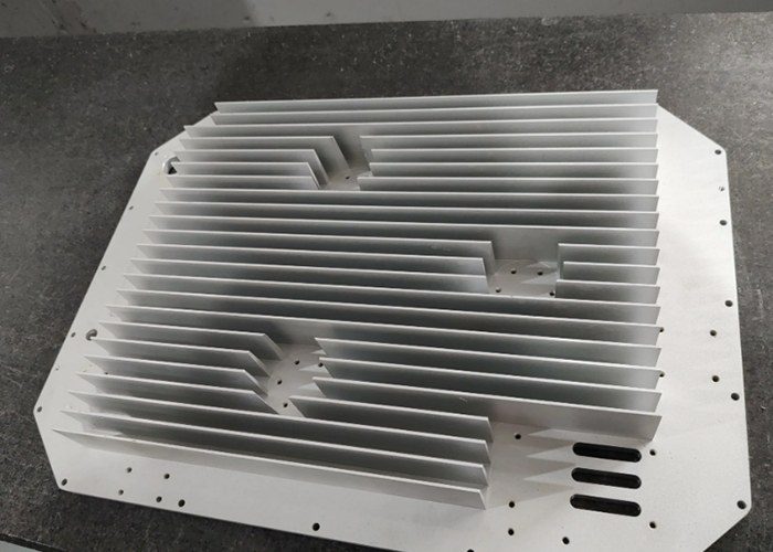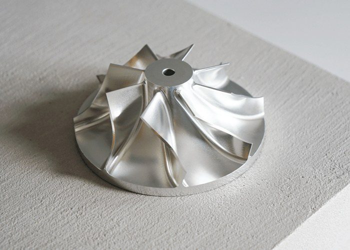
In the realm of modern manufacturing, CNC milling hardware parts are the unsung heroes that transform digital designs into physical reality. Computer Numerical Control (CNC) milling machines are sophisticated systems composed of numerous mechanical components, each playing a critical role in the precise removal of material to create complex parts. Understanding these hardware elements is essential for anyone involved in machining, from hobbyists building DIY machines to engineers specifying production equipment. This article explores the fundamental hardware parts that constitute a CNC milling machine and the ancillary tooling required to make it function effectively.
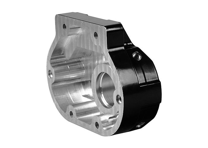
The Structural Foundation: Frame and Axes
The backbone of any CNC milling machine is its frame, which provides the rigidity necessary to withstand cutting forces without deflection. Most industrial machines use cast iron for its excellent vibration-damping characteristics, while DIY builds might utilize welded steel weldments or aluminum extrusions, sometimes filled with epoxy granite for added stability.
Mounted to this frame are the axes, which facilitate motion in Cartesian coordinates. A standard 3-axis machine moves along the X, Y, and Z planes. Each axis consists of two primary components: a suspension system (linear guides or dovetail ways) that ensures straight-line motion, and a drive system (typically ball screws or rack and pinion) that converts rotational motion from the motor into precise linear travel. For more complex geometries, a 4th axis (rotary table) or even 5-axis configurations allow for multi-sided machining in a single setup, drastically improving efficiency and accuracy.
The Heart of the Machine: The Spindle System
The spindle is often described as the heart of the milling machine. The rotating assembly holds and drives the cutting tool. A motor, either directly driven or via a transmission, rotates the spindle at high speeds to cut through materials like aluminum, steel, titanium, and plastics.
At the business end of the spindle is the taper, a precisely ground conical socket where tool holders are inserted. Common tapers include R8, BT, and CAT, with 30-taper spindles being a popular choice for their balance of rigidity and size. To quickly change tools, many machines utilize a powered drawbar, which uses pneumatic or hydraulic force to clamp and release tool holders at the push of a button—a prerequisite for automatic tool changers.
Cutting Tools: From End Mills to Face Mills
The actual material removal is performed by a vast array of cutting tools. The most common are end mills, which cut with both their ends and sides. These come in various configurations:
- Square End Mills: For machining flat surfaces and sharp corners.
- Ball Nose End Mills: Ideal for 3D contouring, mold making, and complex surface machining.
- Roughing End Mills: Feature serrated teeth to break chips into small segments, allowing for rapid material removal.
For facing large, flat surfaces, face mills are the tool of choice. They use multiple indexable inserts and can quickly create a superior surface finish. Other essential cutters include T-slot cutters for workholding slots, thread mills for creating internal and external threads, and drills and reamers for hole-making. The material of the cutter itself—typically High-Speed Steel (HSS), cobalt, or carbide—is selected based on the workpiece material and machining speed.
Workholding: Securing the Workpiece
Without rigid workholding, precision machining is impossible. The most ubiquitous workholding device is the precision machine vise, often a Kurt-style vise, which holds rectangular stock securely. For irregularly shaped parts, T-slot clamping kits with step blocks and studs provide flexibility to secure workpieces directly to the table. Parallels are placed under the workpiece within a vise to ensure it sits perfectly parallel and at the correct height. For high-volume production, custom fixtures and soft jaws (machinable vise jaws) are often employed to hold parts with complex profiles.
Tool Holding and Measurement
Connecting the cutting tool to the spindle requires robust tool holders. ER collet chucks are a popular choice due to their accuracy, wide gripping range, and excellent rigidity. A set of collets in various sizes accommodates different tool shank diameters. For setup, edge finders are used to locate the exact position of the workpiece edge relative to the spindle, while dial test indicators are indispensable for tramming the machine (aligning the spindle perpendicular to the table) and checking part alignment. A Z-axis tool setter allows for quick and accurate measurement of tool lengths, which is critical for multi-tool operations.
Supporting Systems and Accessories
CNC milling hardware also includes crucial support systems. Coolant systems (flood or mist) lubricate the cut, cool the workpiece, and flush away chips. A way oiler automatically lubricates the moving axes to prevent wear and ensure smooth motion. Finally, safety enclosures contain the mess of chips and coolant, protecting the operator and maintaining a clean workspace.
In conclusion, the term “CNC milling hardware parts” encompasses a complex ecosystem of components. From the rigid frame and precise spindles to the specialized cutting tools and secure workholding, each part must work in perfect harmony to achieve the high precision, efficiency, and repeatability that modern manufacturing demands