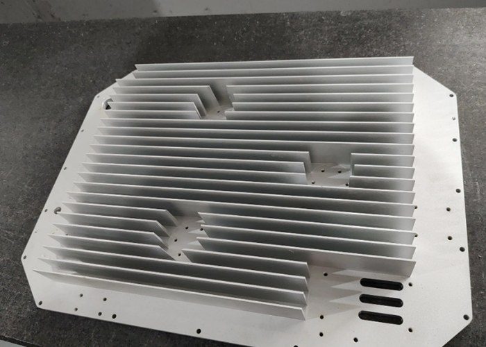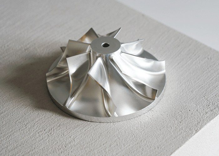
In the vast and intricate landscape of modern manufacturing, few processes embody the marriage of art and science as profoundly as precision milling. At its core, precision milling is a subtractive manufacturing process that uses rotating multi-point cutting tools to remove material from a workpiece. The end product—precision milling parts—are the silent, unassuming workhorses that underpin nearly every critical technology we rely on today, from jet engines and medical implants to smartphone housings and automotive transmission systems. These components are defined not merely by their shape, but by their adherence to tolerances measured in microns—thousandths of a millimeter. This article explores the technical essence, material complexities, quality assurance, and future trajectory of precision milling parts.
The definition of a “precision” part has evolved dramatically over the past two decades. What was considered high accuracy in the 1990s—tolerances of ±0.01 mm—is now routine. Today, advanced CNC (Computer Numerical Control) milling machines routinely achieve geometric tolerances of ±2 to ±5 microns, with surface finishes as smooth as Ra 0.2 µm. This level of precision is achieved through a symphony of rigid machine construction, high-speed spindles (often exceeding 30,000 RPM), advanced toolpath algorithms, and real-time feedback systems. For example, a fuel injector nozzle for a diesel engine contains milling-cut micro-orifices whose diameter and angle directly affect combustion efficiency and emissions. A deviation of just 10 microns could lead to engine knocking, increased pollution, or premature failure.
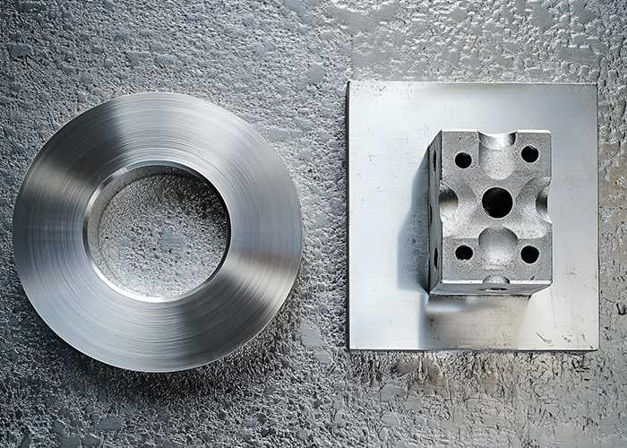
Material selection is a fundamental challenge in precision milling. Unlike 3D printing or casting, milling must contend with the inherent properties of the workpiece—hardness, thermal expansion, chip formation, and work hardening tendencies. Common materials include:
- Aluminum alloys (e.g., 6061-T6, 7075): Favored for aerospace and consumer electronics due to their high strength-to-weight ratio and excellent machinability. However, their softness can lead to built-up edge on cutting tools, requiring sharp geometries and high coolant flow.
- Stainless steels (e.g., 304, 17-4 PH): Used in medical and food processing equipment. Their toughness and tendency to work-harden demand robust tool coatings (e.g., TiAlN or AlCrN) and lower cutting speeds to prevent catastrophic tool failure.
- Titanium alloys (e.g., Grade 5 Ti-6Al-4V): The gold standard for aerospace and orthopedic implants (hip stems, bone plates). Titanium is notoriously difficult to mill due to its poor thermal conductivity—heat concentrates at the cutting edge, causing rapid tool wear. Precision milling of titanium requires specialized strategies: high-pressure coolant (1,000+ PSI), trochoidal toolpaths, and variable-flute end mills.
- Engineering plastics (e.g., PEEK, Delrin): For lightweight, chemical-resistant parts. These require razor-sharp tools and high speeds to avoid melting or burr formation.
The geometry of precision milling parts is where complexity truly escalates. Modern 5-axis milling machines allow cutting tools to approach the workpiece from virtually any direction, enabling the production of parts with undercuts, deep cavities, thin walls, and freeform surfaces. Consider a turbine blisk (integral bladed rotor): the airfoil shapes are twisted, tapered, and separated by narrow channels. Only 5-axis simultaneous milling can generate these forms without multiple setups, which would introduce alignment errors. Similarly, a mold for injection-molded plastic lenses requires optical-grade surface finishes—milling is followed by polishing, but the initial milled surface must be flawless to minimize subsequent work.
The role of software cannot be overstated. CAM (Computer-Aided Manufacturing) software translates CAD models into toolpaths. For precision milling, CAM programmers employ strategies like adaptive clearing (maintaining constant chip load to protect the tool), high-speed machining (light radial depths at high feed rates), and rest machining (automatically targeting leftover material from previous operations). Simulation software verifies the toolpath against the machine kinematics and fixture, detecting potential collisions or gouges before a single chip is cut. In many shops, the CAM programming time for a complex part can exceed the actual machining time by a factor of five.
Quality assurance for precision milling parts is as rigorous as the manufacturing itself. A typical inspection regimen includes:
- CMM (Coordinate Measuring Machine): A touch-probe or laser scanner that measures hundreds of points on a part, comparing them to the nominal CAD model.
- Surface Roughness Tester: Measures Ra, Rz, and other parameters to ensure sealing surfaces or bearing journals meet specifications.
- Optical Comparators & Vision Systems: For rapid measurement of small features, like edge breaks or hole diameters.
- In-process probing: CNC machines now routinely carry touch probes that measure features mid-operation, automatically compensating for tool wear or thermal drift.
Despite its strengths, precision milling faces challenges from additive manufacturing (AM). AM can produce shapes impossible with milling (e.g., internal lattice structures). However, the two technologies are increasingly complementary. Hybrid machines combine laser metal deposition with a milling spindle: the laser builds near-net shape, then the mill finishes critical surfaces to precision tolerances that AM alone cannot achieve. Furthermore, milling remains unmatched in material property preservation—unlike AM, milled parts have no porosity or anisotropic strength issues.
Looking forward, the field of precision milling is being transformed by automation and digitalization. Robotic part loading/unloading, tool condition monitoring (using spindle load or acoustic emission sensors), and AI-driven process optimization are becoming standard in “lights-out” machining cells. Digital twins—virtual replicas of the entire machining process—allow engineers to optimize cutting parameters and predict part deflection before cutting metal. Another frontier is micro-milling: creating parts with features smaller than 100 microns, such as micro-molds for biomedical chips or inkjet nozzle plates.
In conclusion, precision milling parts are far more than simple metal components; they are the physical manifestation of computational geometry, materials science, and mechanical dynamics. Whether it is a bone screw thread that must hold firm in living tissue, a valve spool that slides with micron-level clearance, or a waveguide housing for a satellite’s radar system, these parts enable systems to perform with reliability, efficiency, and safety. As manufacturing technologies evolve, the role of precision milling is not diminishing—it is adapting, becoming smarter, more integrated, and more indispensable than ever. For engineers and machinists who master this craft, the reward is the profound satisfaction of creating something that is both mathematically perfect and eminently useful—a small piece of precision that holds the world together.