
PCD wire drawing dies last 30 to 50 times longer than tungsten carbide dies. On a single die station drawing 0.3mm copper wire at 25 meters per second, that is the difference between replacing a die every two weeks and replacing it once a year. The upfront cost runs 3 to 4 times higher — but the total cost of ownership flips that math. This guide covers material science, grain size selection from 3μm to 50μm, die geometry, and applications across copper, aluminum, stainless steel and precious metals — with ROI data showing exactly when PCD wire drawing dies pay for themselves.
What Are PCD Wire Drawing Dies?
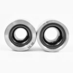
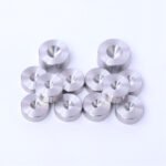
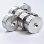
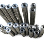
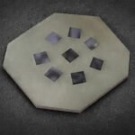
PCD wire drawing dies are precision tooling with a diamond-bearing bore through which metal wire is pulled to reduce its diameter. The working surface is polycrystalline diamond (PCD) — sintered from micron-scale diamond particles under extreme pressure and temperature. Also called polycrystalline diamond drawing dies, these tools cover bore diameters from 0.03mm to 11.0mm.
PCD hardness measures roughly 2.5 times that of tungsten carbide, but tensile strength sits at about 70% of carbide. PCD wire drawing dies excel in finishing passes; carbide still handles roughing with high impact loads.
See how PCD wire drawing dies are specified on our product page.
How PCD Dies Are Made (HPHT Sintering)
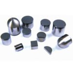
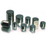
The manufacturing process starts with diamond micro-powder mixed with a metallic binder — typically cobalt or silicon. This mixture goes into an HPHT press at 5 to 8 GPa and 1,400 to 1,600°C, where diamond particles sinter into a dense polycrystalline mass. The PCD blank is bonded to a carbide support ring, then laser-drilled or wire-EDM’d to form the bore, and polished to a mirror finish.
Three core types exist: cobalt-bonded, silicon-bonded, and thermally stable. The same HPHT technology that produces PCD wire drawing dies also creates PCD die blanks for cutting tools. See polycrystalline diamond on Wikipedia for material background; this ScienceDirect study documents HPHT pressure-temperature optimization.
PCD vs ND vs SSD vs TC: Die Material Comparison
Four die materials dominate wire drawing. TC handles rough drawing and harder steels at low cost. PCD covers the broadest range — copper, aluminum, stainless — with 30 to 50 times the lifespan of carbide. SSCD/MCD and natural diamond (ND) serve ultra-fine wire below 0.1mm.
| Material | Hardness | Die Life (vs TC) | Best Wire Type | Cost Range |
| Tungsten Carbide (TC) | HRA 89-93 | 1× (baseline) | Steel, medium Cu/Al | 10-60 |
| PCD (Polycrystalline Diamond) | ~2.5× TC | 10-50× | Cu, Al, stainless | 80-300 |
| Synthetic Single Crystal (SSCD/MCD) | Near ND | 10-20× | Fine wire, precision | 100-500 |
| Natural Diamond (ND) | Highest | 20×+ | Ultra-fine <0.1mm | 200-2,000+ |
For most wire drawing operations, PCD hits the cost-performance balance that neither carbide nor natural diamond can match. ND dies still own the sub-0.05mm segment, but PCD’s 0.03 to 11mm coverage handles over 80% of commercial applications.
Why PCD Outlasts Carbide
Three things change when you switch from carbide to PCD: the die lasts longer, the bore holds tolerance, and the wire comes out smoother.
30-50x Longer Lifespan Than Tungsten Carbide
PCD wire drawing dies last 30 to 50 times longer than tungsten carbide dies on copper and aluminum wire — measured by tonnage. A TC die processes 5 to 20 tons per bore before end-of-life; a PCD die runs 100 to 300 tons. Measured by wire length, a TC die reaches 100,000 to 150,000 meters while a PCD die runs 500,000 to 800,000 meters — a 3 to 8× linear advantage, with the higher multiplier on high-volume lines.
A German copper wire producer in the Baden-Württemberg region drawing 0.3mm enameled wire for electric motor windings replaced TC dies every two weeks when bore ovality pushed wire diameter past tolerance — each changeover costing 15 minutes of downtime and 200 to 300 meters of scrap. With scrap at 3% and 8 to 10 die swaps per month, the plant switched to 5μm PCD wire drawing dies. The first PCD die ran 800,000 meters — five times the TC linear output — before showing ovality. Monthly die changes dropped to one, scrap fell to 0.5%, and the plant recovered 30 hours of lost production per station annually.
Uniform Wear & Hole Diameter Stability
PCD wire drawing dies maintain bore tolerances far longer than carbide. A PCD die holds ±0.001mm tolerance through 200+ tons of copper wire output. A TC die in the same application drifts to ±0.01mm after just 50 tons — ten times the deviation. Operators can simultaneously manage 4 to 5 drawing machines because a PCD die holds tolerance for months, not days.
Superior Surface Finish on Drawn Wire
The PCD bore polishes to Ra ≤ 0.05μm — mirror-level surface roughness. Friction coefficients run 40 to 60% lower than unpolished carbide, which means less heat at the die-wire interface. At 2,000 m/min copper drawing speed, a standard PCD die sees bearing-zone temperatures around 150°C. A high-quality PCD die holds that to 95°C. Lower friction and lower temperature translate to longer life for PCD wire drawing dies and better wire surface quality.
Applications by Wire Material
From 0.03mm gold bonding wire to 11mm steel rod, PCD wire drawing dies — also called diamond wire drawing dies — cover the broadest material range of any die type. But the wrong grain size turns a 50× lifespan advantage into a 5× one.
Copper Wire Drawing
Copper is the largest application for PCD wire drawing dies. Fine copper wire — USB Type-C conductors, enameled magnet wire — calls for 5μm grain. Automotive harness wire runs on 10μm. Approach half-angle: 10° to 14°. Bearing length: 25 to 50% of d. Drawing speed on 5μm reaches 800 m/min; 10μm runs 400 to 600 m/min. PCD dies for copper wire deliver 30 to 50× the lifespan of carbide.
Aluminum Wire Drawing
Aluminum is softer but more abrasive due to its oxide layer. PCD wire drawing dies for aluminum use 5μm or 10μm grain. Approach angle opens to 14° to 18° — wider than copper. Bearing length: 30 to 45% of d. Drawing speeds reach 40 m/s. Aluminum wire drawing dies in PCD outlast carbide by 30 to 50×.
Stainless Steel & High-Carbon Steel
Stainless steel and high-carbon steel demand coarser PCD grain. For 304 stainless, 25μm grain is standard — its impact resistance handles the abrasive alloy. For high-carbon steel like 70#, 50μm grain provides toughness for heavy drawing. Approach angles: 8° to 10° for stainless, 6° to 9° for high-carbon steel.
Critical warning: carbon in steel reacts with diamond above 400°C, degrading the PCD bore rapidly. Control drawing speed and lubrication to stay below that threshold. With proper parameters, 25μm PCD wire drawing dies last 50× longer than TC on 304 stainless.
Special Alloys & Precious Metals
Gold, platinum, semiconductor bonding wire, and medical guidewire use 3μm ultra-fine grain PCD wire drawing dies. At this grain size, the bore achieves near-mirror finish (Ra ≤ 0.05μm), and drawing speeds exceed 1,000 m/min. The tradeoff: 3μm PCD is more brittle. For wire below 0.05mm, natural diamond dies still hold an advantage — but PCD covers 0.05mm to 0.5mm for precious metals at a fraction of ND cost.
How to Select the Right PCD Die
Three specs determine whether a PCD die fits your wire: grain size, binder chemistry, and bore geometry. Get any one wrong and you’ll know within a shift. This wire drawing die selection guide covers each factor with specific parameters.
Grain Size Selection (Coarse vs. Fine PCD)
Grain size is the single most important spec on a PCD wire drawing die. Fine grains (3 to 10μm) prioritize surface finish — mirror-quality wire. Coarse grains (25 to 50μm) prioritize toughness — resisting chipping under impact. Soft metals (copper, aluminum, gold) take fine grains; hard metals (stainless, high-carbon steel) take coarse.
For copper wire drawing, the recommended PCD grain size is 5μm for fine wire (0.05-0.2mm, enameled/USB Type-C) or 10μm for general copper harness wire (0.2-1.0mm).
An Italian producer drawing 0.8mm 304 welding wire for Tier 1 automotive suppliers hit a wall on surface quality. With 10μm PCD dies, wire roughness measured Ra 0.4μm — but automotive customers demanded Ra ≤ 0.25μm. The engineer upgraded to 25μm grain PCD and tightened the approach angle from 12° to 9°. The coarser 25μm grain held its edge longer against the abrasive 304 stainless — counterintuitively, the tougher grain resisted micro-chipping that was degrading surface finish with the 10μm die. Die life jumped from 30 tons to 150 tons per hole — a 5× improvement. Surface roughness dropped to Ra 0.2μm, and tolerance tightened from ±0.005mm to ±0.001mm.
| Grain Size | Best Wire Material | Wire Diameter | Drawing Speed | Surface Finish | Die Life vs TC |
| 3μm (ultra-fine) | Gold, platinum, bonding wire | ≤0.05mm | Up to 1000+ m/min | Ra ≤ 0.05μm (mirror) | 30-100× |
| 5μm (fine) | Copper, aluminum, enameled wire | 0.05-0.2mm | Up to 800 m/min | Ra ≤ 0.05μm | 30-50× |
| 10μm (medium) | Copper harness, stainless welding wire | 0.2-1.0mm | 400-600 m/min | Excellent | 20× |
| 25μm (medium-coarse) | 304 stainless, tire bead, elevator rope | 1.0-5.0mm | Medium-low | Ra ≥ 0.2μm | 50× |
| 50μm (coarse) | High-carbon steel (70#) | ≥5.0mm | Low | Rough | Highest toughness |
Uking offers PCD wire drawing dies across all standard grain sizes from 3μm to 50μm, with custom geometries available for non-standard wire specifications. In our experience at Uking Diamond, the most common grain-size mistake we see is shops defaulting to 10μm for everything — then wondering why their stainless wire surface looks rough after a few shifts.
Cobalt-Based vs. Silicon-Based PCD
Most PCD wire drawing dies use cobalt as the binder — industry standard, cost-effective, and well-suited for copper and aluminum. Silicon-based PCD (TSPCD) contains no metallic catalyst, giving it better thermal resistance for high-temperature drawing of stainless or high-carbon steel. The tradeoff is higher cost and slightly lower impact toughness. A dedicated cobalt-based vs. silicon-based PCD comparison guide is coming soon.
Die Geometry: Reduction Angle & Bearing Length
Die geometry determines drawing force, wire quality, and die life. PCD wire drawing dies have five bore zones: entry, lubrication, reduction (approach), bearing, and exit. Approach half-angle and bearing length are the two parameters that most affect performance.
| Wire Material | Approach Half-Angle | Bearing Length (% of d) | Notes |
| Copper | 10°-14° | 25-50% | Wider angle for softer metal |
| Aluminum | 14°-18° | 30-45% | Largest angle — Al deforms easily |
| Stainless Steel (304) | 8°-10° | 50% | Tighter angle, longer bearing |
| High-Carbon Steel (70#) | 6°-9° | 40-60% (dry drawing) | Tightest angle, longest bearing |
Optimizing the approach angle reduces drawing force by 8 to 12% and extends die life by 20 to 30%. Standard die dimensions follow ISO 1684; a wire drawing die geometry design guide covering five-zone theory will follow.
PCD Die Maintenance & Regrinding
When to Regrind vs. Replace
PCD wire drawing dies can be reground multiple times — similar to natural diamond dies, which typically allow 2 to 3 regrinds. The decision depends on wear severity:
- Light wear — Repolish the bore at the original diameter to restore finish.
- Moderate wear — Recut to the next larger diameter, changing approach angle and bearing.
- Severe wear — Replace when cracks or chipping make regrinding uneconomical.
The trigger point is when bore diameter deviation exceeds half the tolerance band. Regrinding recovers 20 to 40% of a new die’s cost each cycle. Repolishing requires precision resin bond diamond grinding wheels for die regrinding — controlled material removal prevents micro-cracking.
We’ve seen PCD dies that operators wanted to scrap after one regrind go on to deliver another 200,000 meters after a proper recut. Send the wire material, current die spec, and bore measurement — we’ll tell you whether regrinding or replacement makes more economic sense.
How to Extend PCD Die Service Life
Die life depends on more than the die itself. Proper installation, optimized lubrication, controlled drawing speed, and regular bore inspection each extend die life — skip any one and you’ll see the difference in bore wear within a week. A daily bore diameter check catches wear before it reaches the tolerance limit. A dedicated guide on 7 proven ways to extend PCD die service life is coming soon.
Cost Analysis: PCD vs. Tungsten Carbide (TCO)
The unit price of a TC die looks attractive: 30 to 80. PCD wire drawing dies cost 80 to 300. On paper, carbide wins. But paper ignores downtime, scrap, and changeover labor.
A Mexican Tier 1 automotive wire harness supplier running 0.5mm copper wire 16 hours a day burned through TC dies every three weeks. Ten replacements per year at 40 each cost 400, plus ten 15-minute changeovers at 50 each — 900 per station annually. A 10μm PCD die at 200 ran six months without replacement. Break-even hit at 283 tons — about 60 days. Annual cost per station dropped from 900 to 200 — saving 700 — and scrap fell from 5% to 1.5%.
The break-even point lands around 283 tons of wire output — typically 60 days on a standard copper line. A detailed PCD vs. tungsten carbide cost analysis with TCO calculator and per-meter cost breakdown will follow.
Why Choose Uking PCD Wire Drawing Dies
As a PCD wire drawing die manufacturer serving Europe, the Americas, and the Middle East, Uking Diamond focuses on five capabilities:
- No MOQ — Order from 1 Piece. Test a single die on your line before committing to volume.
- Full Grain Size Coverage (3μm to 50μm). From ultra-fine precious metal wire to coarse high-carbon steel.
- Application Engineering Support. Send us your wire material, diameter, and drawing speed — we recommend the optimal grain size and geometry.
- Die Regrinding Service. Extend die life and recover 20-40% of new die cost.
- Custom Die Geometry. Bore diameters from 0.03mm to 11.0mm, custom approach angles, and PCD core types (cobalt-based, silicon-based, thermally stable).
Our Specifications & Capabilities
Uking manufactures custom PCD wire drawing dies with bore diameters from 0.03mm to 11.0mm, grain sizes from 3μm to 50μm, tolerance of ±0.001mm, and bore surface finish of Ra ≤ 0.05μm. Cobalt-based, silicon-based, and thermally stable PCD core types are available with custom approach angles and bearing lengths.
Request a Quote
Whether you need a single die for testing or a full set for production, Uking supports orders from one piece with no MOQ. Send your wire material, diameter, and drawing speed — we will recommend the right PCD wire drawing dies for your line.
Request a quote for PCD wire drawing dies →
Frequently Asked Questions
How long do PCD wire drawing dies last?
PCD wire drawing dies last 30 to 50 times longer than tungsten carbide dies (measured by tonnage). On copper wire, a single PCD die processes 500,000 to 800,000 meters — or 100 to 300 tons of wire — before measurable wear requires regrinding or replacement.
What is the difference between PCD and natural diamond dies?
PCD dies are sintered from synthetic diamond particles, offering higher toughness at lower cost. Natural diamond (ND) dies use a single crystal, delivering superior finish for ultra-fine wire below 0.1mm but are brittle and cost 5 to 10 times more. PCD covers 0.03 to 11mm; ND covers 0.01 to 0.5mm.
Can PCD dies draw stainless steel wire?
Yes. For 304 stainless, 25μm coarse-grain PCD is recommended for its impact resistance. Keep drawing temperatures below 400°C — carbon in steel reacts chemically with diamond at higher temperatures, causing rapid die degradation.
How much do PCD wire drawing dies cost?
PCD wire drawing dies cost 80 to 300 per piece, depending on diameter, grain size, and tolerance grade. While 3 to 4 times more expensive than tungsten carbide (30-80), PCD dies pay for themselves within approximately 60 days on high-volume copper lines through reduced downtime and die changes.
When should I regrind vs. replace a PCD die?
- Light wear — Repolish at the original diameter to restore finish.
- Moderate wear — Recut, changing to the next size and adjusting approach angle.
- Severe wear — Replace when cracks or chipping make regrinding uneconomical.
PCD dies typically allow 2 to 3 regrinds.
What wire materials can PCD wire drawing dies handle?
PCD wire drawing dies handle copper, aluminum, stainless steel, high-carbon steel, galvanized wire, welding wire, tungsten, molybdenum, and precious metals including gold and platinum. Match grain size to material: fine grains (3-10μm) for soft metals, coarse grains (25-50μm) for hard metals.
How do I choose the right PCD grain size for my wire?
Match PCD grain size to your wire material and diameter: 3μm for precious metals and ultra-fine wire (≤0.05mm), 5μm for copper and aluminum fine wire (0.05-0.2mm), 10μm for general copper and stainless welding wire (0.2-1.0mm), 25μm for 304 stainless and bead wire (1.0-5.0mm), and 50μm for high-carbon steel (≥5.0mm).
Start With One Die
You know the scenario: a TC die goes oval mid-shift, the wire drifts out of tolerance, and 300 meters of copper goes to scrap before anyone notices. PCD wire drawing dies don’t eliminate that risk entirely — but they stretch the window from two weeks to six months.
The numbers hold up across every application we’ve tracked: 30 to 50 times longer die life by tonnage, ±0.001mm tolerance stability, Ra ≤ 0.05μm surface finish, and a 60-day break-even point. Whether you draw 0.3mm enameled copper at 25 m/s or 0.8mm 304 stainless welding wire, the right grain size and die geometry determine whether your investment pays off in weeks or months.
Start with a single die on your highest-changeover station. Let the production data make the case.
- Email: [email protected]
- WhatsApp: +8613126851888
- Inquiry form: Request a quote for PCD wire drawing dies →